In-shoe measurement of midsole properties
Bachelor’s Dissertation (69%)
The aim of this project was to collect data from extended running tests using the Midsole Compression Measurement System developed by a previous student and identify any problems with the system, then develop an in-shoe system for evaluating the impact of a running shoe midsole on plantar pressure measurements. Midsole compression and thickness was shown to decrease during runs, after workarounds were found for two issues with the MCMS. Incomplete recovery data of the midsole was also recorded, suggesting complete midsole recovery within a 24 hour period. The plantar pressure system was developed to a point which allowed validation using an Instron 3382, as well as the comparison of force measurements above and below the midsole of the ASICS Megablast at three key points of the shoe. A 50% reduction in force was found at the forefoot and midfoot, with an 85% reduction in force at the rearfoot, where the midsole is thickest. The system was not able to achieve in-vivo running testing, as initially desired, however recommendations are included for the development of such a system.
Several issues were identified with the existing system as developed by another student, mostly due to data handling. Theoretical fixes were developed for this project however the system was not developed to the point of testing such fixes.
The main challenge of this project was the simultaneous measurement of plantar pressure above and below a midsole foam in a running shoe. Firstly, plantar pressure was proxied as the force measured at a certain point on the shoe as this was simpler than a true measurement of pressure and functionally the same as approximating the pressure based on a localised force measurement (cutting down on calculations such as force / area helps reduce processing demands). A Seeed XIAO nRF52840 was used to record voltage outputs from a voltage divider circuit connected to piezoresistive force sensors, allowing the system to measure the force at a certain point on the shoe once calibrated. The Seeed board could handle 6 analogue inputs, so three locations on the shoe were chosen based on a rearfoot strike Centre Of Pressure map, with two sensors per location.
The force sensors chosen for this project were the Interlink Electronics Force Sensitive Resistor (FSR) 402’s, a Shunt Mode Force Sensing Resistor with a sensing range of 0.1N to 600+N dependent on the resistor used in the potential divider circuit. For this project a 500 Ohm potentiometer was used, tuned to 270 Ohm however for further developments this resistance would be reduced for greater resolution at higher forces.
Testing (and initial calibration) was conducted using an Instron 3382 which applied known forces to each sensor position in turn, beginning with 10N and peaking at 600N. For lab testing the Seeed board was connected directly to a laptop to prevent any potential issues with wireless data transfer from corrupting the data samples. The Seeed board handled the conversion from voltage to force based on the calibrated values recorded earlier in testing, which were then printed to the Serial port on the laptop where a Python script could read in the force values and format them into a CSV file. These CSV files were then loaded into Excel for data visualisation.
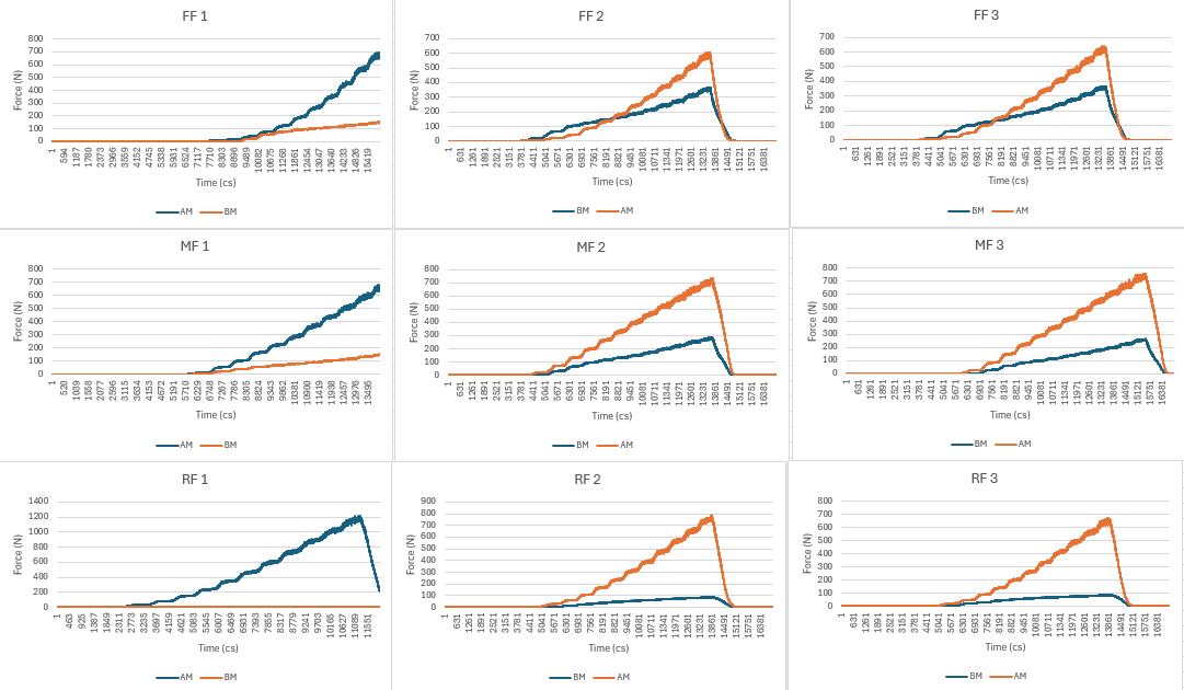
Force vs Time plots for each sensor location, comparing force outputs above the midsole (AM) vs below the midsole (BM)
As can be seen in the figure above, there were a few issues with data collection. A number of tests were cut short by the python script, noise increased significantly as force increased and occasionally sensors did not record data. These issues are not overly concerning, as a full system would measure data continuously without reliance on a timed python script to record samples, a reduction in the resistance of the potentiometer would allow for greater resolution at higher forces and a fully soldered system would not face as many issues with sensors disconnecting.
Now, the fun part: what did we actually find. Despite the issues with data collection, some very interesting results came out of this testing. Firstly, the forefoot and midfoot conditions performed similarly, possibly due to having similar midsole thicknesses. The only real difference was in the comparative shape of their graphs, however this could be due to the testing method as the forefoot condition may have involved the shoe shifting beneath the Instron at lower forces. Nevertheless, at peak force both forefoot and midfoot conditions showed a 50% force reduction across the midsole. At the rearfoot condition, with maximal midsole thickness for the shoe, force reduction was found to be 85% across the midsole.
How would I improve this system in the future?
Firstly, the used of film-based flexible circuit boards would allow for a better self-contained system, housing the potential divider circuits next to the sensors, cushioned by the insole and midsole (and using plain resistors instead of potentiometers to cut down on size). This would allow for 6 sensors to each feed into the Seeed board, housed on the laces of the shoe. The addition of an ANT+ module to communicate data with a Garmin device should help address the data transfer issues discovered when testing a prior students system, as the ANT wireless system is custom built for high-data transfers as compared to low energy Bluetooth. This would then need a ConnectIQ app to store this data on the Garmin device and export to a phone app (likely built using MATLAB for data handling and processing).
Thank you for reading about this project, if you would like to know more about the development of this system or have suggestions on how it could be developed further, please reach out via E-mail or on LinkedIn.